|
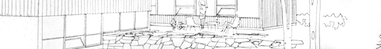
Design
Sketch
View
larger image.
This is a series of sketches on a single page showing the
front and rear elevations of the house as well as a quick
sketch of the interior of the living room looking towards
the dining room. Note the inclusion of an Eames molded plywood
chair in the sketch - very iconic. |

|
Area Topography
View
larger image.
A diagram showing the areas to be developed in South Calgary
by Plateau Land Development corp. Hard to believe that this
is all considered 'inner city' 50 years on. 50th avenue, 3
blocks south of the Trend House site was the city limits up until the early 60s. |
|
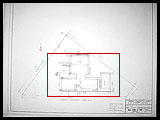
Drawing #1
- Plot Plan
View
larger image.
A diagram showing the areas to be developed in South Calgary
by Plateau Land Development corp. Hard to believe that this
is all considered 'inner city' 50 years on... |

|
Drawing #2
- Ground Floor Plan
View
larger image.
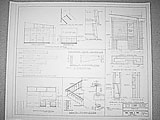
One of the most interesting drawing showing the layout and
construction details of tyhe ground floor. Interestingly,
it shows a much extended patio and extensive use of flagstone
which was not actually carried out (I can only assume for
cost reasons). Also it shows where all the various wood products
are to be applied, colors, finishes etc. |

|
Drawing #3
- Lower Floor Plan
View
larger image.
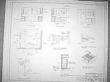
Drawing of the lower floor and the crawlspace below the main
floor. By moving the mechanical systems to a room on the lower
floor the house it eliminates the need for a basement. |

|
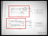
Drawing #4
- North and South Elevations
View
larger image.
Views of the house from the street (south) and Elbow Drive
(north) sides. |
|
Drawing #5
- East and West Elevations
View
larger image.
Views of the house from the east and west sides. |

|
Drawing #6
- Sections and Garage Elevations
View
larger image.
Longditudinal and lateral cross-sections of the house showing
various structural details. Includes details of the kitchen
venting system which used a louvered fascia with a hinged
panel on the inside to control venting to the kitchen. Unfortunately
since it's construction it has been sealed shut. |

|
Drawing #7
- Wall and Window Details
View
larger image.
Drawings showing the construction of the walls and the window
sections. |
|
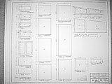
Drawing #8
- Window and Glass Schedules
View
larger image.
Drawings of the shape and dimensions of all the windows in
the house. |
|
Drawing #9
- Other Details
View
larger image.
Detailed plans for the fireplace, staircase, beams and built-in
furniture int he dressing room. |
|
Drawing #10
- Kitchen Layout and Details
View
larger image.
Detailed plans for the kitchen counters and cabinets. Shows
that originally the kitchen included some custom designed
features like a special cutlery drawer, a pull out towel storage
area and a removable waste bin. |

|
Drawing #11
- Heating Details Ground Floor
View
larger image.
Plans showing the layout of the heating system. One thing
that continues to perplex me is why the heating system was
divided up the way it was. The problem is twofold: first,
the main furnace services the entire front of the house and
the upstairs, while the second furnace services only the bottom
of the house. It would have made more sense to divide the
house and service the front of the house independantly of
the back. Secondly, the thermostat for the upper and main
floor is located in the master bedroom. Since the upstairs
is so much better insulated than the front of the house the
heater is turned only when the upstairs is cold which means
that by that time the front of the house is freezing. |

|
Drawing #12
- Heating Details Lower Floor
View
larger image.
Plans showing the layout of the heating system on the lower
floor. Another problem with the original layout is that the
runs from the furnace to the front of the house are very long,
and not very efficient. One way we are thinking of addressing
this is to relocate a furnace to below the main floor and
linking the HVAC to the rear of the house. |